Home

Selv tak Perth Blackborough Sammenbrud boundary conduction mode buck converter as Saucer kilometer kollidere

Limit between continuous and discontinuous conduction modes for the... |  Download Scientific Diagram
Limit between continuous and discontinuous conduction modes for the... | Download Scientific Diagram

A digital predictive critical conduction mode buck converter control method  | Semantic Scholar
A digital predictive critical conduction mode buck converter control method | Semantic Scholar

Why do we operate converters in discontinuous conduction mode? - Quora

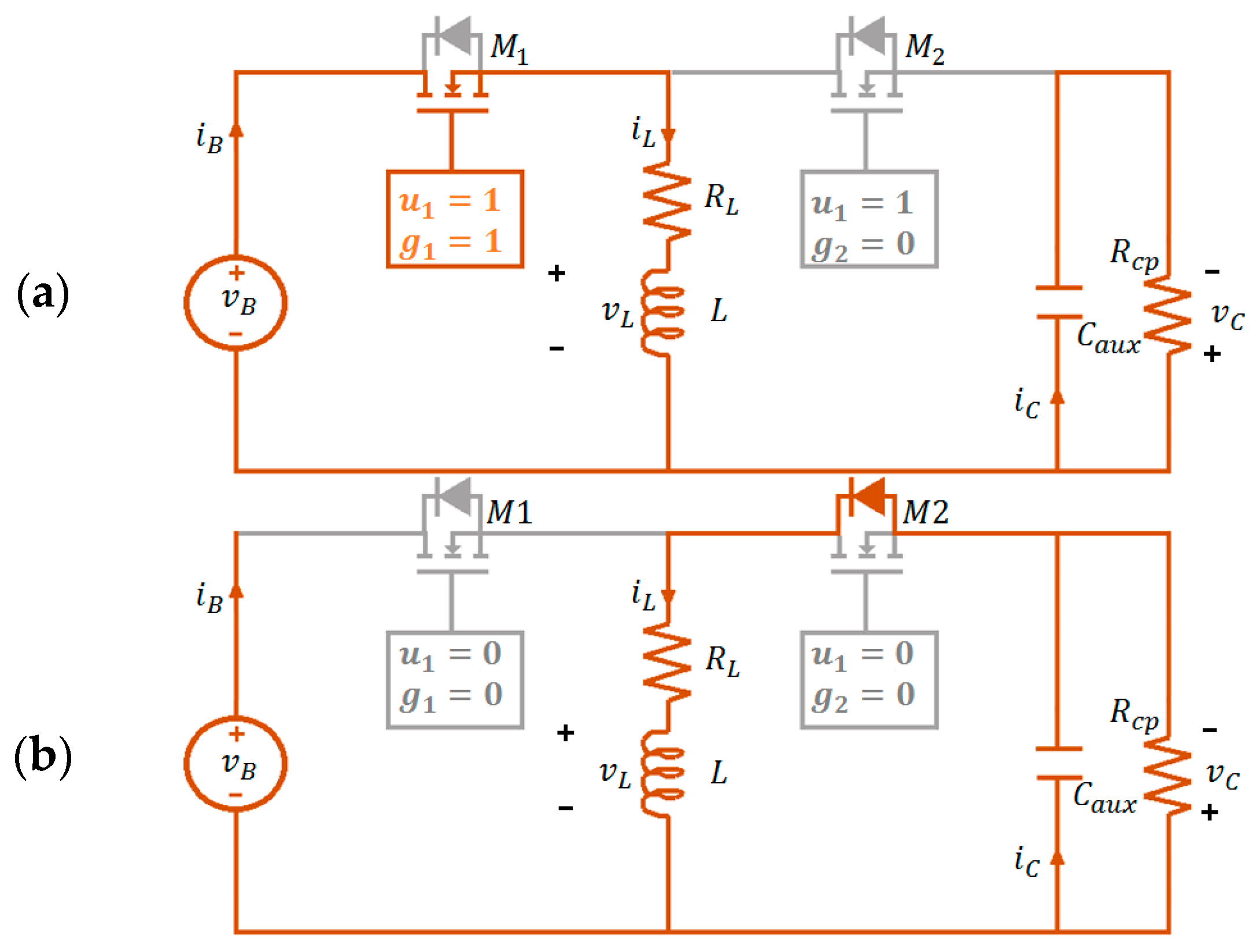
Energies | Free Full-Text | Control of the Bidirectional Buck-Boost  Converter Operating in Boundary Conduction Mode to Provide Hold-Up Time  Extension
Energies | Free Full-Text | Control of the Bidirectional Buck-Boost Converter Operating in Boundary Conduction Mode to Provide Hold-Up Time Extension

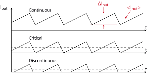
What are Buck Converters? - Basic Operation and Discontinuous Mode vs.  Continuous Mode | Overview of Design Examples of AC-DC Non-isolated Buck  Converters | TechWeb
What are Buck Converters? - Basic Operation and Discontinuous Mode vs. Continuous Mode | Overview of Design Examples of AC-DC Non-isolated Buck Converters | TechWeb

Figure 2 from Variable On-Time (VOT)-Controlled Critical Conduction Mode  Buck PFC Converter for High-Input AC/DC HB-LED Lighting Applications |  Semantic Scholar
Figure 2 from Variable On-Time (VOT)-Controlled Critical Conduction Mode Buck PFC Converter for High-Input AC/DC HB-LED Lighting Applications | Semantic Scholar
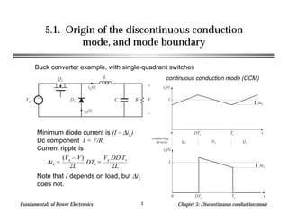
Chapter 05
Chapter 05

Interleaved boundary conduction mode (bcm) buck power factor correction  (pfc) converter
Interleaved boundary conduction mode (bcm) buck power factor correction (pfc) converter

Energies | Free Full-Text | Control of the Bidirectional Buck-Boost  Converter Operating in Boundary Conduction Mode to Provide Hold-Up Time  Extension
Energies | Free Full-Text | Control of the Bidirectional Buck-Boost Converter Operating in Boundary Conduction Mode to Provide Hold-Up Time Extension

Step-down buck converter - imperix power electronics

The Discontinuous Conduction Mode | SpringerLink

The Difference between CCM and DCM Explained | Article | MPS

Figure 1 from Small-signal modeling of the PWM boost DC-DC converter at  boundary-conduction mode by circuit averaging technique | Semantic Scholar
Figure 1 from Small-signal modeling of the PWM boost DC-DC converter at boundary-conduction mode by circuit averaging technique | Semantic Scholar

Figure 1 from Size reduction of the inductor in critical conduction mode  PFC converter | Semantic Scholar
Figure 1 from Size reduction of the inductor in critical conduction mode PFC converter | Semantic Scholar

Buck-Boost Converter Voltage Equation in Discontinuous Conduction Mode  (DCM) - YouTube
Buck-Boost Converter Voltage Equation in Discontinuous Conduction Mode (DCM) - YouTube

Figure 1 from An optimal peak current mode control scheme for critical  conduction mode (CRM) Buck PFC converter | Semantic Scholar
Figure 1 from An optimal peak current mode control scheme for critical conduction mode (CRM) Buck PFC converter | Semantic Scholar

Buck-Boost Converter Critical Inductance Value - YouTube

Solved 2. [30] Consider the Buck-Boost converter shown in | Chegg.com

Discontinuous Conduction Mode of Simple Converters - Technical Articles

A critical conduction mode bridgeless flyback converter | Semantic Scholar

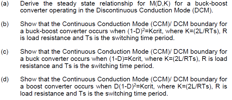
Solved (a) Derive the steady state relationship for MD,K) | Chegg.com

Figure 3 from Boundary Conduction Mode Control of a Boost Converter With  Active Switch Current-Mirroring Sensing | Semantic Scholar
Figure 3 from Boundary Conduction Mode Control of a Boost Converter With Active Switch Current-Mirroring Sensing | Semantic Scholar

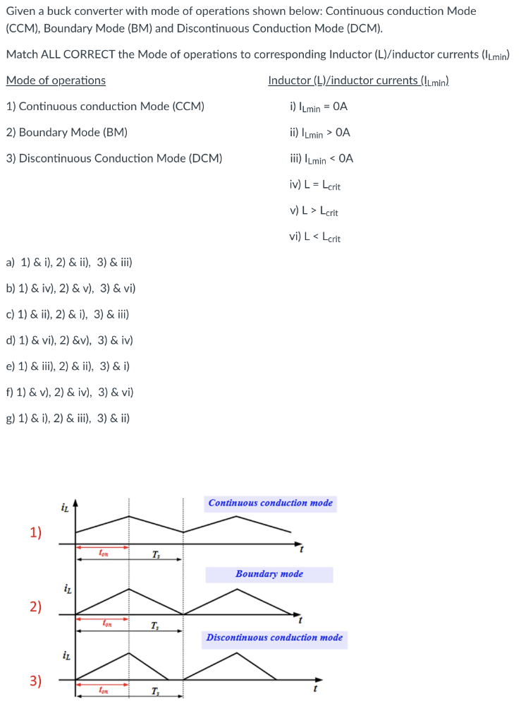
Solved Given a buck converter with mode of operations shown | Chegg.com